
Section V
paragraphs 5-47 to 5-48
Figure 5-6
boards. Use caution when removing them to avoid
damaging mounted components. The Part Number
for the assembly is silk screened on the interior of
the circuit board to identify it. Refer to Section VI
for parts replacement and Part Number information
5-47. The etched circuit boards are a plated-through
type. The electrical connection between sides of the
board is made by a layer of metal plated through the
component holes.
When working on these boards,
observe the following general rules.
TM 11-6625-1614-15
Model 410C
c. Component lead hole should be
cleaned
before inserting new lead.
d. To replace components, shape new leads and
insert them in holes. Reheat with iron and add
solder as required to insure a good electrical
connection.
e. Clean excess flux from the connection and
adjoining area.
a. Use a low-heat (25 to 50 watts) small-tip
f. To avoid surface contamination of the printed
soldering iron, and a small diameter rosin
circuit, clean with weak solution of warm water
core aoider.
and mild detergent after repair. Rinse thoroughly
with clean water. When completely dry,
spray
b. Circuit components can be removed by
lightly with Krylon (#1302 or equivalent).
placing the soldering iron on the component
lead on either aide of the board, and pulling up
5-48. CHOPPER ASSEMBLY INSTALLATION.
on lead. If a component is obviously damaged,
clip leads as close to component as possible
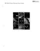
a. Figure 5-6 describes the physical orien-
and then remove. Excess heat can cause the
tation of chopper assembly on printed circuit
circuit and board to separate, or cause damage
board. Note location of chopper assembly serial
to the component.
number in relation to circuit board pins.
Figure 5-6. A4 Chopper Assembly Installation
01566-2
5-15


 England
  Deutschland
  France
  Italia
  Polska
  United Kingdom
  Россия
  Nederland
  España
  Magyarország
  Sverige
  România
  Portugal
  Colombia
  Suomi
Suomi  New Zealand
  Česká republika
  Türkiye
  Danmark
  日本
日本