
Power Supply Replacement Instructions
for the MLS 304/306/406
1. Disconnect the power cord from the switcher.
2. If the switcher is rack mounted, remove it from the rack.
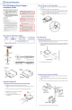
3. Remove the 14 screws (8 on the top and 3 on each side) that secure the
switcher’s top cover, as shown below.
Lift cover
straight up.
Remove (14)
screws from
top and sides.
4. Lift the cover straight up and off.
5. Disconnect both power supply cables, as shown below. Disconnect the two-
pin power input cable from the power supply. Disconnect the power supply
output cable from the switcher’s main PCB board (not the power supply).
Remove the
screw.
Power Supply to be Removed
Remove the screw.
Disconnect the
cable from the
main board
end.
Remove the screw.
Remove the screw.
Disconnect the
cable from the
power supply’s
2-pin connector.
6. Remove the four screws that secure the power supply to the base of the
switcher. Retain at least two of the screws for installation of the new power
supply.
Extron Electronics, USA
1230 South Lewis Street
Anaheim, CA 92805
800.633.9876 714.491.1500
FAX 714.491.1517
Extron Electronics, Europe
Beeldschermweg 6C
3821 AH Amersfoort, The Netherlands
+800.3987.6673 +31.33.453.4040
FAX +31.33.453.4050
Extron Electronics, Asia
135 Joo Seng Rd. #04-01
PM Industrial Bldg., Singapore 368363
+800.7339.8766 +65.6383.4400
FAX +65.6383.4664
Extron Electronics, Japan
Kyodo Building, 16 Ichibancho
Chiyoda-ku, Tokyo 102-0082
Japan
+81.3.3511.7655 FAX +81.3.3511.7656
www.extron.com
68-1262-04
Rev. A
09 07
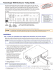
Install
standoffs (2).
Plug the PCB’s power output cable
to the power supply’s 2-pin power
input connector.
Install screws (2).
Plug the output
cable from fhe
power supply to
the PCB’s power
input connector.
10. Connect the switcher’s power output cable to the power supply’s 2-pin power
input connector. See the previous illustration.
11. Connect power output cable from the power supply to the switcher’s power
input connector. See the previous illustration.
12. Install the insulator and attaching screws that were removed in step 7.
Position insulator under
the heat sink.
Fasten the
insulator to the
standoffs.
Heat Sink
C The insulator must be tucked under the heat sink to protect components
from possible damage.
13.
Replace the top cover and reinstall the 14 screws removed in step 3.


 England
  Deutschland
  France
  Italia
  Polska
  United Kingdom
  Россия
  Nederland
  España
  Magyarország
  Sverige
  România
  Portugal
  Colombia
  Suomi
Suomi  New Zealand
  Česká republika
  Türkiye
  Danmark
  日本
日本