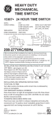
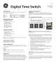
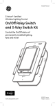
GE switch PBe Manual

PDF Manuals
34 Pages
English
PDF Manuals
34 Pages
English


ManualsOcean is one platform for online manuals. You can find and view the user manuals online easily. There are more than 600,000 PDF Manuals in our database. We collect and add new user manuals every day so that you can find the right user manual for your search. You can view all of Online User Manuals for free.


 England
  Deutschland
  France
  Italia
  Polska
  United Kingdom
  Россия
  Nederland
  España
  Magyarország
  Sverige
  România
  Portugal
  Colombia
  Suomi
Suomi  New Zealand
  Česká republika
  Türkiye
  Danmark
  日本
日本